

Towards Software-Defined Delay Tolerant Networks

1
Paul G. Allen School of Computer Science & Engineering, University of Washington, Seattle, WA 98195, USA
2
NASA Glenn Research Center, Cleveland, OH 44135, USA
*
Author to whom correspondence should be addressed.
Network 2023, 3(1), 15-38; https://doi.org/10.3390/network3010002
Submission received: 27 September 2022
/
Revised: 17 November 2022
/
Accepted: 24 December 2022
/
Published: 28 December 2022
(This article belongs to the Special Issue Advanced Technologies in Network and Service Management)
Abstract
:This paper proposes a Software-Defined Delay Tolerant Networking (SDDTN) architecture as a solution to managing large Delay Tolerant Networking (DTN) networks in a scalable manner. This work is motivated by the planned deployments of large DTN networks on the Moon and beyond in deep space. Current space communication involves relatively few nodes and is heavily deterministic and scheduled, which will not be true in the future. It is unclear how these large space DTN networks, consisting of inherently intermittent links, will be able to adapt to dynamically changing network conditions. In addition to the proposed SDDTN architecture, this paper explores data plane programming and the Programming Protocol-Independent Packet Processors (P4) language as a possible method of implementing this SDDTN architecture, enumerates the challenges of this approach, and presents intermediate results.
1. Introduction
Space communication has largely been restricted to a bent-pipe architecture that allows nodes on Earth to communicate with science assets in space by sending data through a series of relay satellites. Although this is an effective method of communication at a small scale, it is not feasible for large-scale communications. In the near future, the number of nodes in space is going to exponentially increase as the number of science missions on the Moon increases. NASA’s LunaNet architecture and ESA’s Moonlight initiative aim to address this issue by developing the infrastructure required to provide robust communication and navigation services for assets on the Moon. The enabling technology that will be used to improve this communication is the Delay Tolerant Networking (DTN) computer networking architecture [1,2].
DTN is an architecture that enables communication over links that are expected to be unreliable, intermittent, and have high latency [3]. Environments that exhibit these link characteristics include underdeveloped or low-resource regions, areas impacted by natural disasters, and outer space [4]. DTN enables communication by forwarding data in a store-and-forward manner, so that data are not dropped but simply delayed when links are intermittent or have high latency. Currently, the deployment of DTN in space has only been executed on the small scale, such as on the International Space Station (ISS) and its communications with ground stations via a DTN network [5]. DTN networks face issues with scalability that are not seen in traditional networks due to the core issue of having intermittent links. For example, the inability to quickly receive acknowledgements or propagate information about links that unexpectedly went down makes reliably routing data a difficult task. One large class of DTN routing algorithms tackles this issue in a deterministic manner by providing contact plans to nodes in the network that dictate at what times links will be available [6]. However, this assumes that either the contact plan will always be accurate, or that when link behavior changes a contact plan can be updated and reliably distributed to the nodes in the network, ironically over high-latency and intermittent links. While this may work on the small scale for small DTN networks, this is not a practical method for large-scale networks that span multiple network operators over several intermittent links. A solution must be found in order to enable the eventual deployment of the Solar System Internet, a cross space agency collaboration that aims to deploy a DTN network that spans all planets in our solar system [7].
To tackle this issue of management of large DTN networks, we propose a Software-Defined Delay Tolerant Networking (SDDTN) architecture that adapts Software-Defined Networking (SDN) techniques, an approach to managing large traditional networks in a centralized manner, to the DTN environment. This SDDTN architecture tackles the issue of reacting to changes in the network in a challenged networking environment through a hybrid approach where networking decisions can be determined, distributed, and executed at both a local-neighborhood scale and at the individual node level.
Additionally, in this paper we examine one possible path towards implementing a SDDTN architecture via data plane programming. In traditional SDN networks, networking switches are deployed that communicate with a centralized controller to send telemetry and receive decisions. However, there is currently no hardware that is able to understand the protocols behind DTN, as all implementations of the DTN protocols have been in software. We attempted to use the Programming Protocol-Independent Packet Processors (P4) (P4 is a registered trademark of Open Networking Foundation (ONF) and is a programming language used under Open Source license) language to create a program for a networking switch that would enable the switch to (1) understand the requisite DTN protocols and (2) communicate with an SDN controller. The specific program we aimed to create is a network middlebox that would be able to translate between the two primary versions of the Bundle Protocol (BP) in use by current and future DTN networks (BP version 6 and version 7), for reasons discussed in Section 4.2. A proof-of-concept BP translator was developed that enabled DTN nodes to communicate despite utilizing different BP versions.
This paper is laid out as follows: Section 2 provides necessary background details on DTN, Bundle Protocol, and routing within DTN networks; Section 3 explains SDN and our proposed SDDTN architecture; Section 4 describes and provides context for our approach towards implementing a SDDTN; Section 5 presents our proof of concept, details the challenges we faced, and evaluates its capabilities; and Section 6 contains our concluding thoughts and recommended next steps.
2. Delay Tolerant Networking Background
This section contains background information on DTN and related work. Section 2.1 provides an overview of the history, architecture, and implementations of DTN used for experiments in this paper. In Section 2.1, the two versions of Bundle Protocol are explained and their differences highlighted. Lastly, Section 2.1 discusses the current state of DTN routing from the perspective of scalability.
2.1. DTN Overview
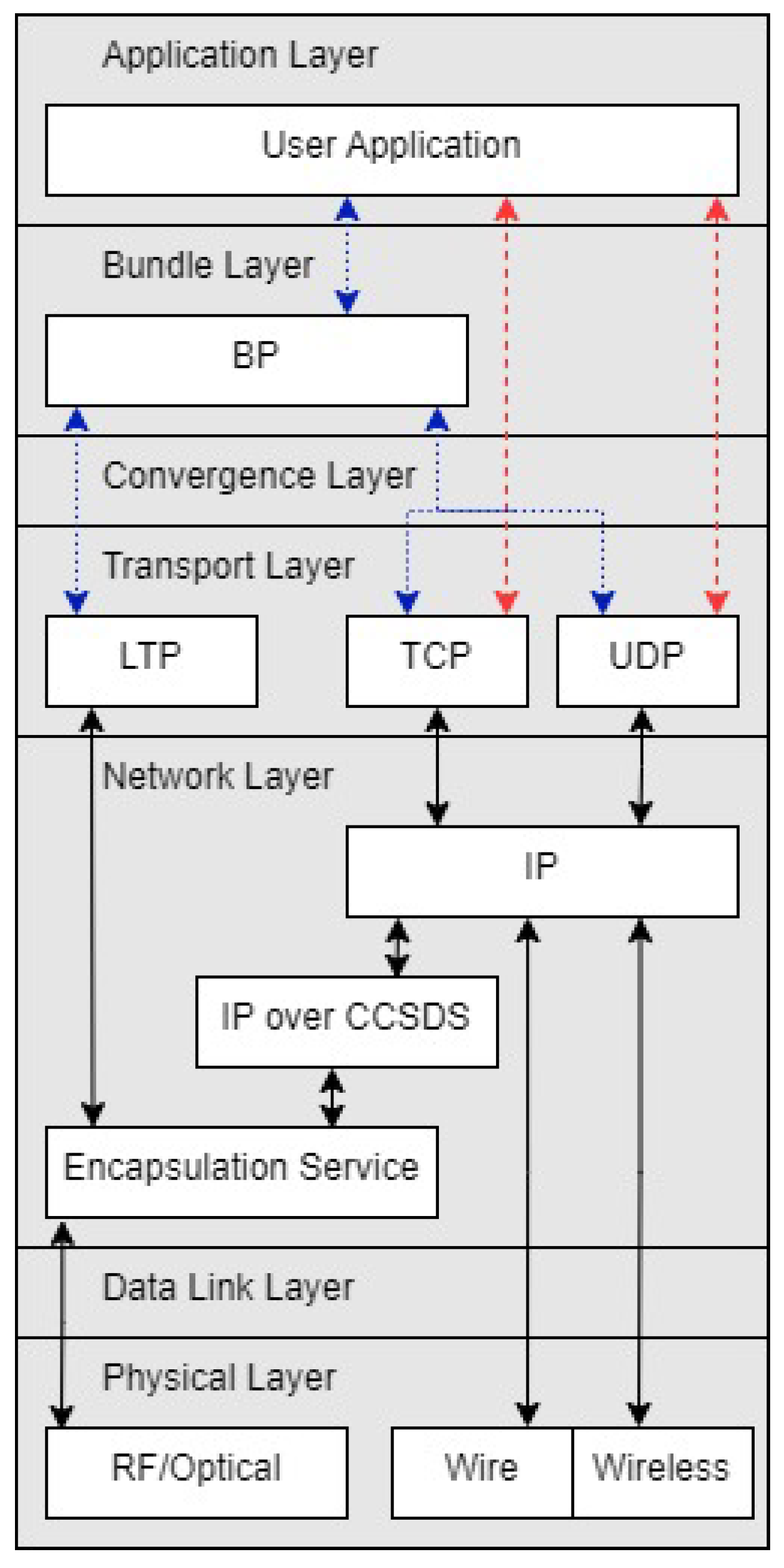
In 2003, the DTN architecture was introduced in [8] to provide network connectivity to environments that the TCP/IP model failed to address, such as low-resource regions, outer space, or areas impacted by natural disasters that have intermittent and high latency links [3,4]. DTN is an overlay network with the primary protocol being BP and the protocol unit of data being bundles. BP is analogous to a more robust version of Internet Protocol (IP), featuring endpoint identifiers, intermittent links, store-and-carry forwarding, security, and extendability. BP can run over any underlying network with a respective convergence layer adapter, including the TCP/IP suite of protocols [3]. Figure 1 provides an overview of what the network stack of a DTN network looks like when overlaid on a TCP/IP network. The bundle layer is able to utilize various transport layer protocols such as the User Datagram Protocol (UDP), the Transmission Control Protocol (TCP), and the Licklider Transmission Protocol (LTP) through the use of a protocol specific convergence layer adapter, e.g., the TCP Convergence Layer (TCPCL) [9].
A formal document detailing the DTN architecture was introduced in 2007 [3], followed by the specification of experimental BP version 6 (BPv6) [10], the first documented version of a protocol for DTN. Throughout the years, BPv6 was implemented, deployed, and tested in an experimental manner, leading to the first officially standardized version of the protocol in January 2022, with the introduction of BP version 7 (BPv7) [11].
The tests described in this paper use two DTN implementations developed by NASA. The first is the Interplanetary Overlay Network (ION) implementation developed by NASA’s Jet Propulsion Laboratory [12]. ION has been deployed on the ISS [5] as a DTN gateway and has served as a reference implementation for many space-related DTN projects. To this reason, it was designed with resource-constrained flight-like hardware in mind. It features Bundle Protocol version 6 and 7, Licklider Transmission Protocol (LTP) [13], Contact Graph Routing (CGR) [14], and many space-related applications.
The High-rate Delay Tolerant Networking (HDTN) project was developed by NASA Glenn Research Center [15]. HDTN is focused on developing a performance optimized, modular DTN architecture capable of supporting rates of 1 Gigabit per second and greater [16,17,18,19]. Similar to ION, HDTN supports Bundle Protocol version 6 and 7, LTP, CGR, file transfer applications, and related tools. In addition, HDTN has been shown to be interoperable with ION and HDTN is able to detect what version of BP it received but can only send or respond with the BP version it have been configured to use.
2.2. Bundle Protocol
BPv6 and BPv7 are similar in their core layout. Bundles are made up of various blocks of information that are necessary for nodes in a DTN network to execute store-and-carry forwarding. There are only two required blocks in a bundle: a primary block (the beginning of a bundle) and a payload block (the end of a bundle). Between these required blocks, there are optional extension blocks that can include information such as hop limits, information about the previous/sender node, and class of service [10]. While BPv6 and BPv7 bundles have the same abstract bundle structure, the way bundles are encoded and the specific fields included in each block varies greatly.
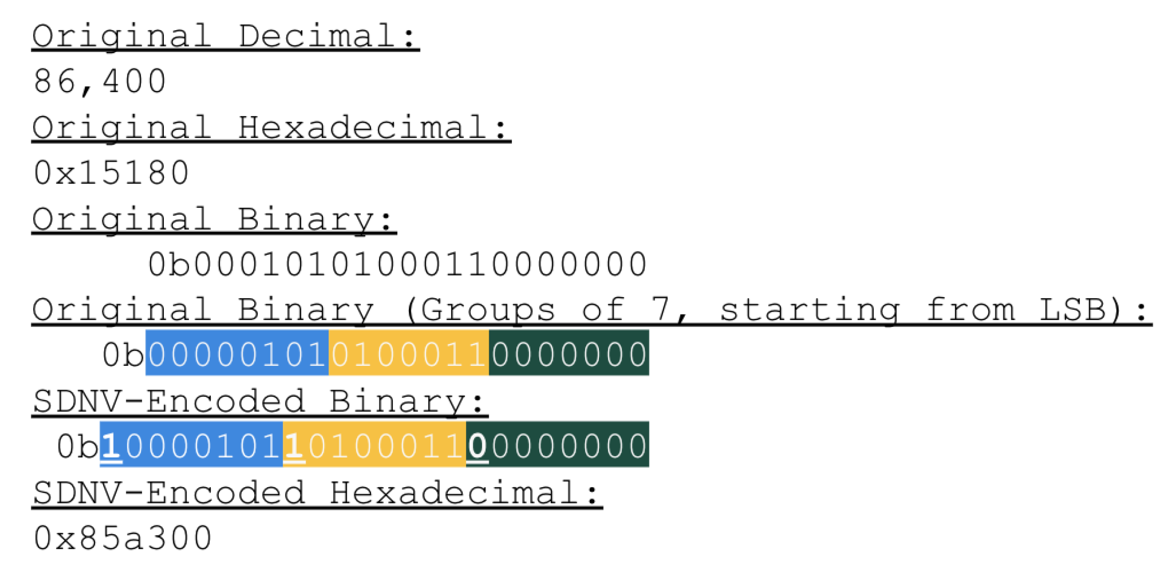
BPv6 uses the Self-Delimiting Numeric Value (SDNV) scheme to encode fields within bundles [10,20]. Compared to network protocols that have fields with pre-defined bit widths, SDNV preserves channel capacity (by avoiding a minimum bit width) and allows for future extensibility and scalability (by avoiding a maximum bit width) at the overhead cost of an additional bit for every seven bits. The SDNV encoding scheme encodes any data into several octets of bits, where the seven least significant bits (LSB) encode the original data, and the most significant bit (MSB) of an octet determines whether or not it is the last octet of data. An MSB with a value of 0 indicates that it is the last octet of data, with all other octets having an MSB of 1. Figure 2 shows an example of the decimal value 86,400 encoded using SDNV. Most fields within BPv6 bundles are encoded using the SDNV format, such as the bundle processing flags, block lengths, and endpoint identifiers (EID).
EIDs are the names used for various parties within a DTN network such as the source and destination nodes. It is important to note that EIDs are names and not addresses, meaning an EID does not provide any hierarchical information. EIDs are represented as Uniform Resource Identifiers (URI) and can be arbitrarily long. BPv6 utilizes EID Dictionaries, an array of value pairs representing EIDs (a scheme name and scheme-specific value), to minimize overhead [10]. EID Dictionaries act as a single source of information for all EIDs that will be referenced within a given bundle so that subsequent fields can reference an EID by simply referencing offsets within the dictionary rather than encoding the full EID.
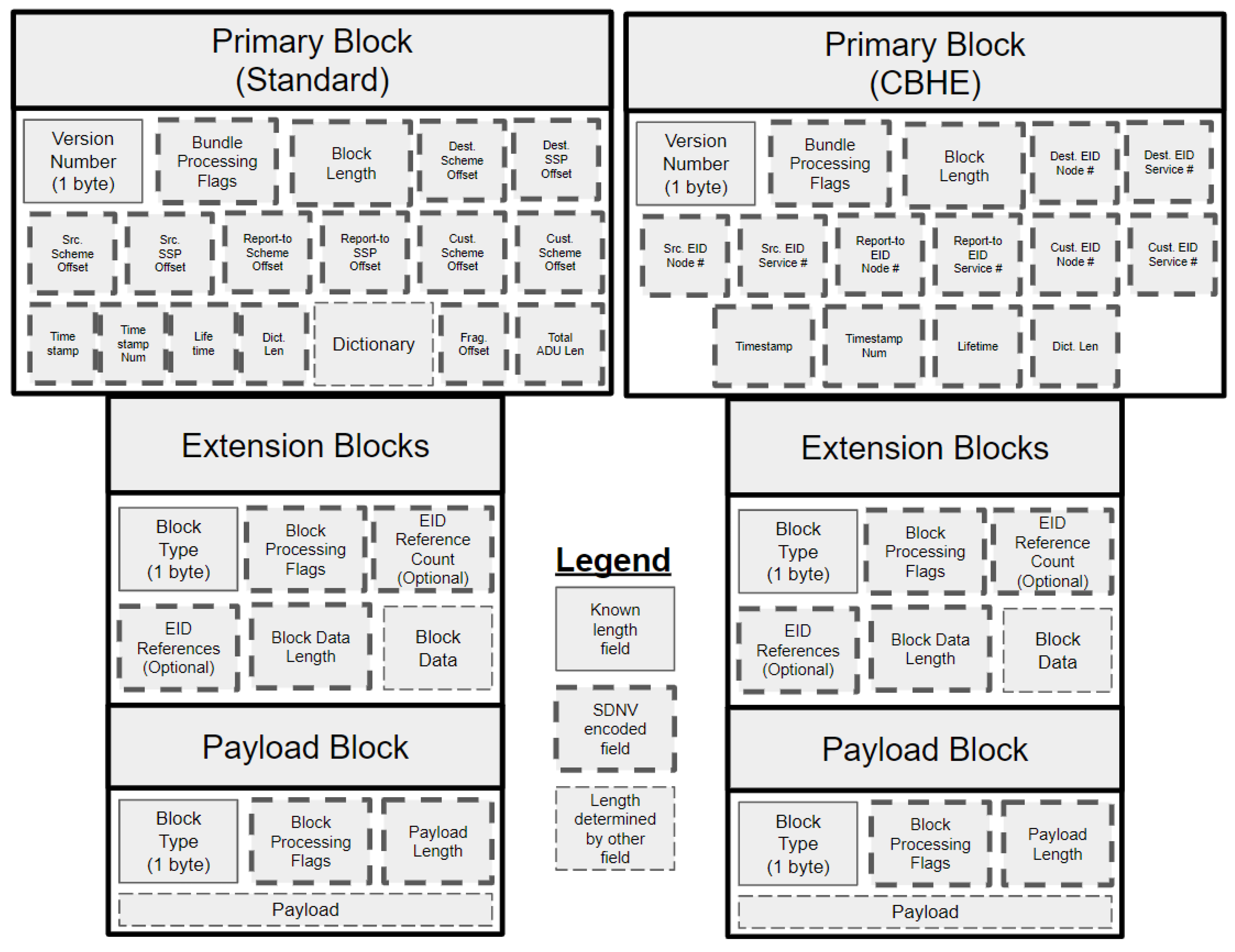
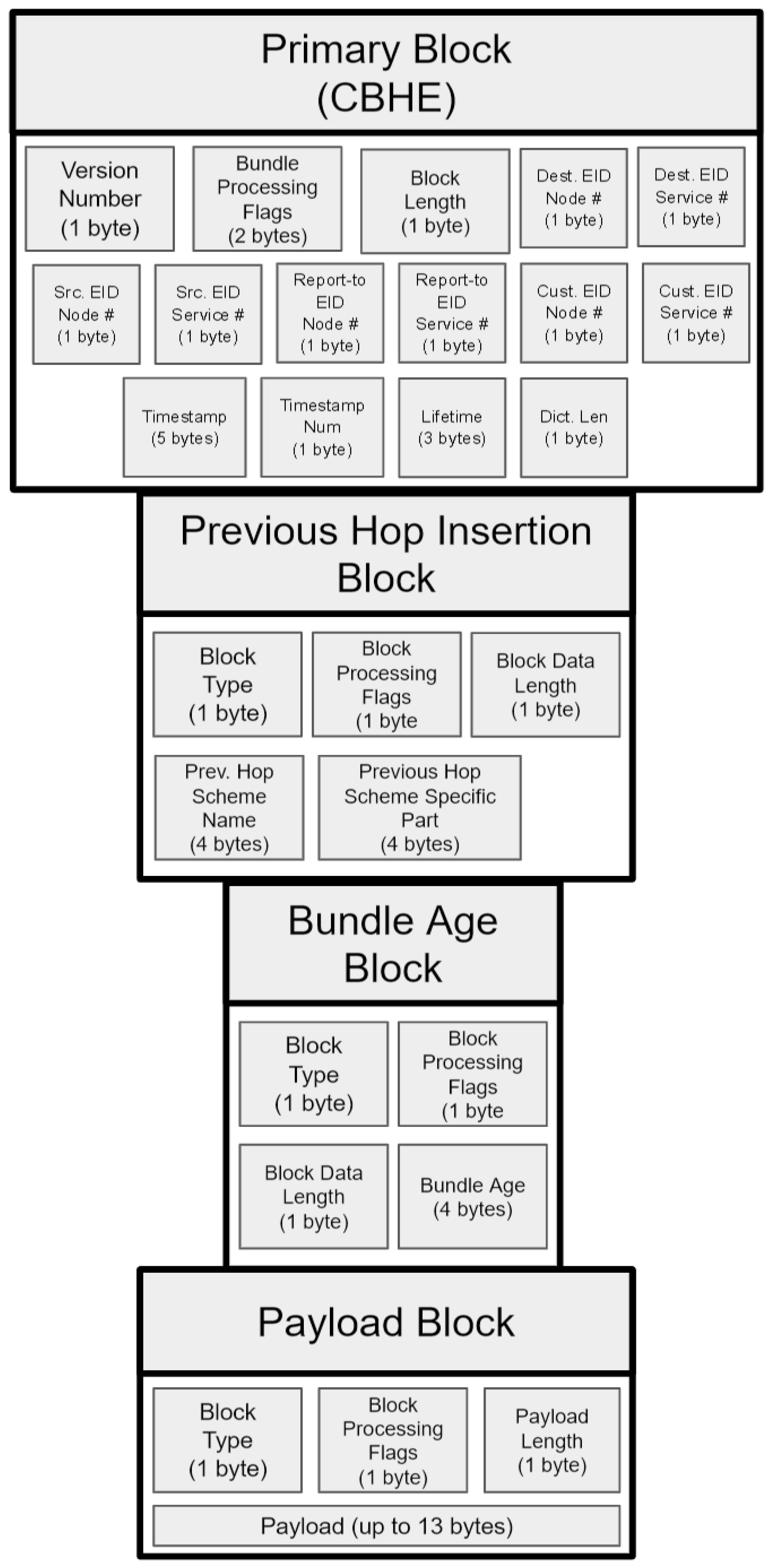
Introduced four years after the BPv6 specification, Compressed Bundle Header Encoding (CBHE) is a mechanism to further preserve bandwidth, by avoiding encoding EID dictionaries entirely [21]. In a situation that meets the requirements for CBHE, encoding a dictionary can be skipped, with EID information encoded as ipn scheme (ipn is one of the URI schemes used to encode EIDs) EIDs in the primary block’s source EID, destination EID, report-to EID, and custody EID offset field. With CBHE, bundles can be transmitted without a dictionary, and the dictionary can then be rebuilt at the receiving node. Figure 3 provides a general diagram of two layouts of BPv6 bundles: a standard bundle, and a bundle using CBHE. Here one can view the Extension and Payload blocks are the same but the Primary block of CBHE removes the dictionary and its counterparts. BPv6 CBHE format was used for the experimentation portion in this paper.
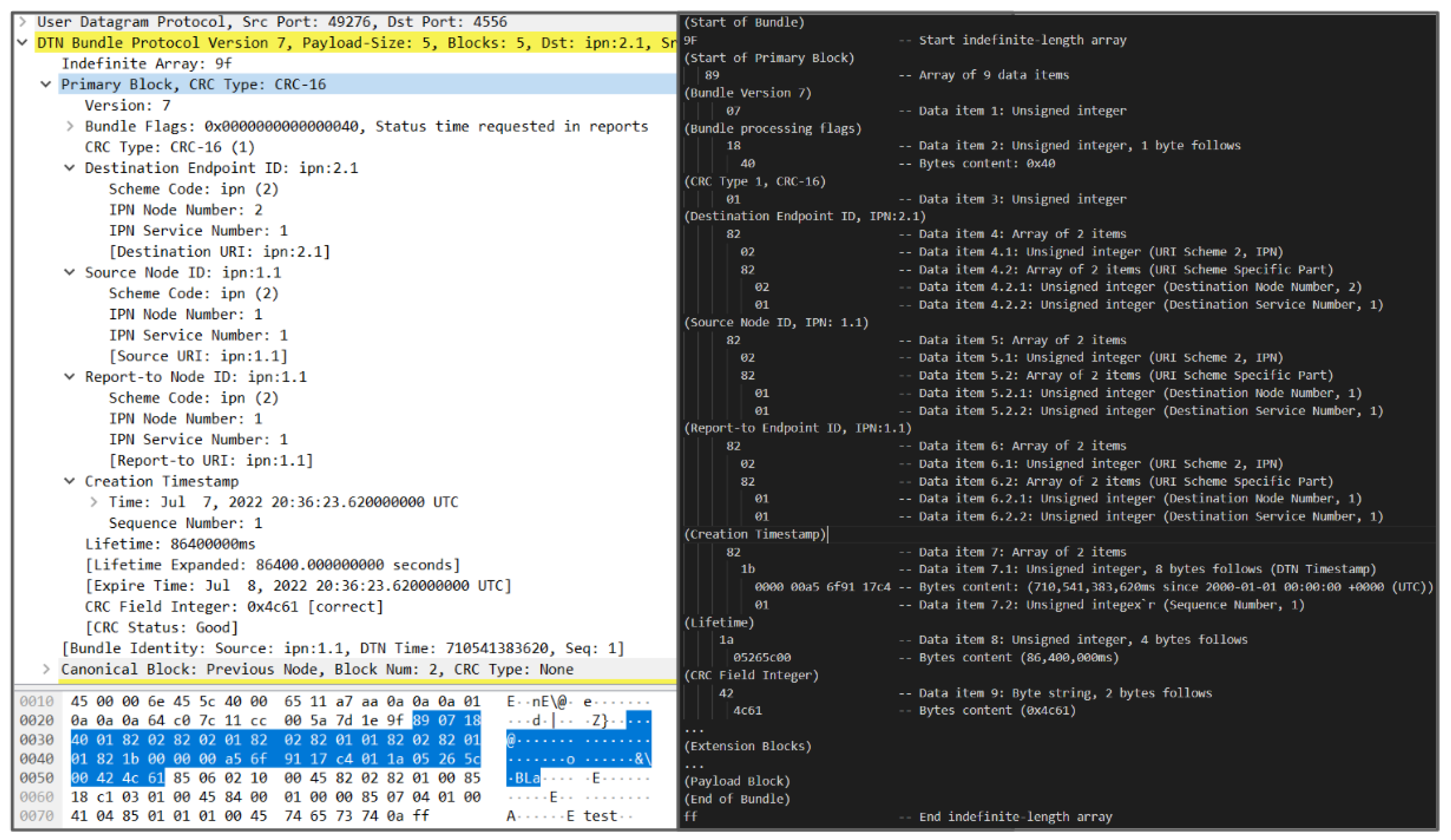
BPv7 changes the encoding of bundles from being SDNV-formatted to using Concise Binary Object Representation (CBOR) [11]. CBOR provides a structured serialization format, while maintaining flexibility and compactness. The layout of the CBOR data model is a superset of JavaScript Object Notation (JSON), containing several data types, e.g., integers, strings, maps, and arrays. An instance of a CBOR data type is a data item [22]. In BPv7, a single bundle is a CBOR indefinite-length array, comprised of an indefinite number of blocks which are encoded as CBOR definite-length arrays [22]. The end of a bundle is terminated by a stop code (0xFF). An example BPv7 bundle and a decoding of its primary block is shown in Figure 4, which demonstrates how BPv7 bundle fields are encoded as a nested array of various data types rather than the flat representation of SDNV fields that was seen in BPv6.
Alongside an encoding change, a couple of components were relocated away from the official BP specification in BPv7 and may be moved to other sections of the DTN protocol suite. One feature moved away from BP in BPv7 is class of service [11]. BPv6 bundles were able to request a certain class of service through bundle processing flags in the primary block, such as bulk, normal, or expedited class of service [10]. According to an Internet Engineering Task Force (IETF) draft (See the Bundle Protocol Extended Class of Service draft: Available online: https://datatracker.ietf.org/doc/html/draft-burleigh-dtn-ecos-00, accessed on 1 September 2022), class of service may be handled as a BPv7 extension block. Another feature moved away from the BPv7 specification is custody transfer, also implemented through bundle processing flags, which is used to request another node to take responsibility for a given bundle. An IETF draft indicates that custody transfer may be placed within the bundle-in-bundle encapsulation (BIBE) specification (See the Bundle-in-Bundle Encapsulation draft: Available online: https://datatracker.ietf.org/doc/html/draft-ietf-dtn-bibect-03, accessed on 1 September 2022).
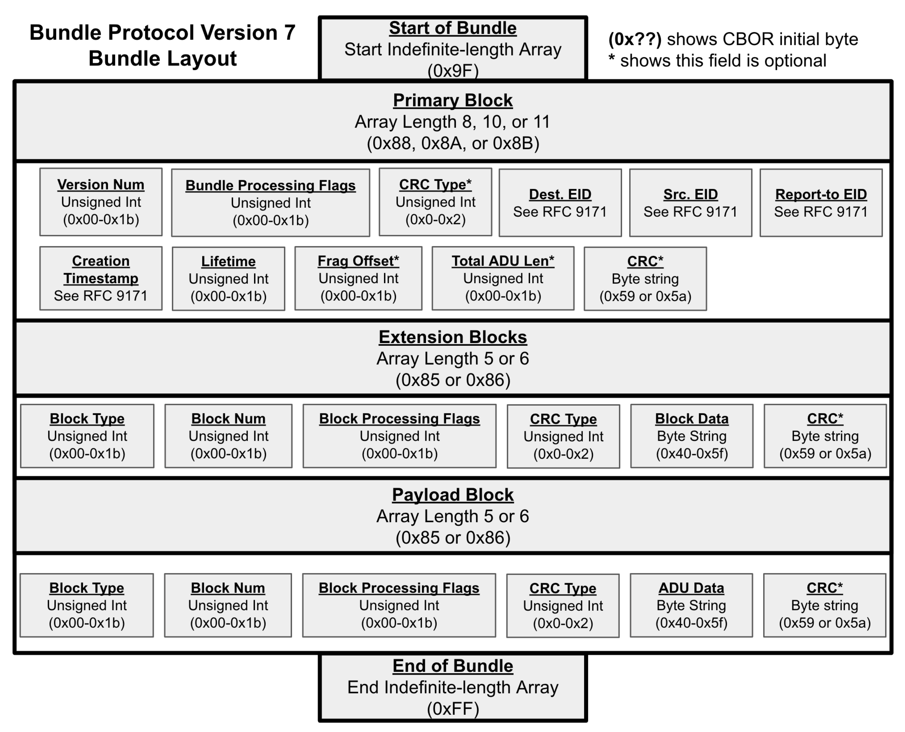
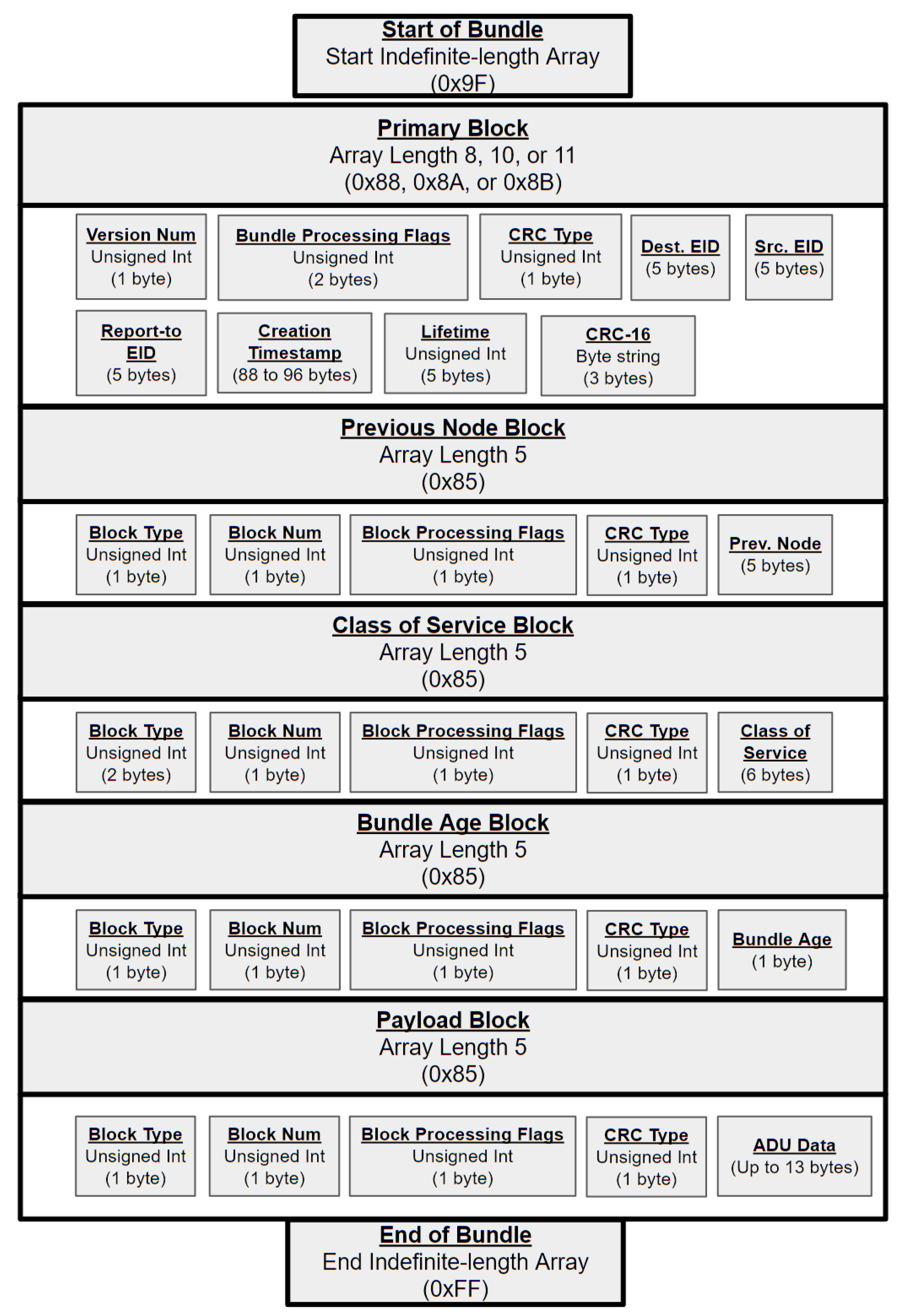
Lastly, BPv7 adds optional error detection to bundle blocks through the form of Cyclic Redundancy Check (CRC) error-detecting codes (CRC-16 and CRC-32). This enables DTN nodes to verify the data integrity of received bundles [11]. A general diagram of the layout of BPv7 bundles is shown in Figure 5, showcasing the various CBOR data types that each bundle block and block field is encoded as. Note that while BPv6 and BPv7 look similar, there are significant differences in how they are encoded and the fields that are included.
2.3. Space DTN Routing and Scalability
DTN routing algorithms can vary based on the amount of knowledge assumed by the algorithm [23]. For example, there are flooding-based algorithms that send replicated bundles throughout the DTN network to reach its destination at the cost of congesting the network, at the benefit of not needing any detailed information about the structure of the network [24]. On the other hand, there are algorithms that take advantage of pre-existing knowledge of the network topology to make smarter decisions about where bundles should be sent, assuming one is able to acquire up-to-date and accurate network state information. Contact Graph Routing (CGR) is a routing method that assumes DTN nodes have access to contact plans that provide information about when links are available to determine the best route to send bundles.
CGR has become the de facto choice for routing within space DTN networks due to current space DTN networks consisting of nodes with heavily scheduled and deterministic behavior and CGR’s ability to provide reliable bundle delivery [6]. An active area of research is scaling CGR to work on large and nondeterministic DTN networks. A CGR relies on the assumption that DTN nodes will always have access to up-to-date contact plans, which may not necessarily be true if unexpected events occur or space network nodes are no longer heavily scheduled and deterministic. CGR also relies on the assumption that given a contact plan, a best route can be computed in a reasonable amount of time, which may not be true if the contact plan grows with the size of the network.
Opportunistic Contact Graph Routing (OCGR) was introduced in [25] as a middle-ground between algorithms that assume full knowledge of the network and algorithms that assume zero knowledge of the network. In OCGR, nodes can learn new contacts in an opportunistic manner and add these contacts to their contact plan. This reduces the need for carefully scheduled contact plans and enables on-the-fly adaptation. OCGR would be useful for the increasingly growing space network environment, in which creating contact plans for the entire network may no longer be feasible.
To reduce contact plan size and route computation time, the idea of hierarchical and inter-regional routing was introduced in [26]. In this hierarchical system, the network would be divided into regions (that are possibly operated by separate entities), and each region would have its own contact plan. The problem of global contact routing is then subdivided into intra-regional routing problems and inter-regional routing problems. Experimental testing of this hierarchical format showed promising results as a possible solution to CGR scalability.
In addition to the drawback of contact plan distribution and scalability, many DTN routing methods are typically implemented at the application layer, meaning that IP-layer routing is not addressed and must be handled by another mechanism. This detail will depend on the complexity of the network(s) and the number of network interfaces a given node has. SDN can help alleviate this issue in several ways. An intelligent SDN switch can be aware of both the DTN application-level routes and the IP-level routing. The switch could also independently route packets at the hardware level and abstract this decision away from the client node, simplifying the DTN routing decisions. Previous work has explored using SDN to implement IP-layer load balancing for DTN networks [27].
3. Software-Defined Delay Tolerant Networking Architecture
Given that the scaling of space DTN routing is still an active area of research, an SDN approach to managing scalability in space DTN networks is proposed. SDN is a technique used by network operators to manage their large networks in a scalable manner by dividing their networks into a control plane and data plane, and centralizing the control plane. The data plane consists of network routers that handle the task of forwarding data through the network; however, the routes and policies of this data forwarding are dictated by a centralized SDN controller. A benefit of this architecture is that it enables network operators to monitor and rapidly change the behavior of large portions of the network, assuming a control plane link exists. These are desirable qualities for a space DTN network operator that may want to change the behavior of their network as needed due to changing technical or political constraints. However, because SDN requires control plane links between the SDN controller and the nodes within the network, it is unclear how this can be applied to the DTN environment where links are inherently intermittent.
There is previous work in applying SDN to DTN networks in a terrestrial military context in Last-Mile Tactical Edge Networking (TEN) [28]. This is a particular adaptation of SDN where any node within a local DTN network can become the SDN controller via an election algorithm. This solves the issue of each node maintaining a link to a SDN controller by making any node within a local network eligible to become an SDN controller. However, this architecture was designed for a terrestrial military context which has properties that may not be desirable for the space environment. Firstly, nodes in this last-mile TEN can be thought of as highly mobile drones in a harsh battlefield environment where there are several different types of data flows that require different levels of Quality of Service (QoS). For example, a live video feed is data that must never be stored and it is imperative that an SDN controller is available to ensure that this video feed has priority over other data. This highly dynamic and fast-paced environment are conditions that are not as relevant in the less dynamic space environment. Secondly, the ability for a controller to always be present is required in this environment to ensure that these QoS guarantees are always met, which may not be an important in a space network and too restrictive of a constraint. Lastly, a downside of this highly dynamic design is that the controller is not a constant device, which means that a network operator wishing to access the controller and change QoS policies would not be able to unless they can determine which device is the controller at any given moment. While this is not something needed for the Last-Mile TEN environment, the ability to have human intervention in network behavior is a desirable property for space networks which are more stable and subject to political and social constraints. The SDDTN approach we propose keeps the constraints of the space DTN environment in mind.
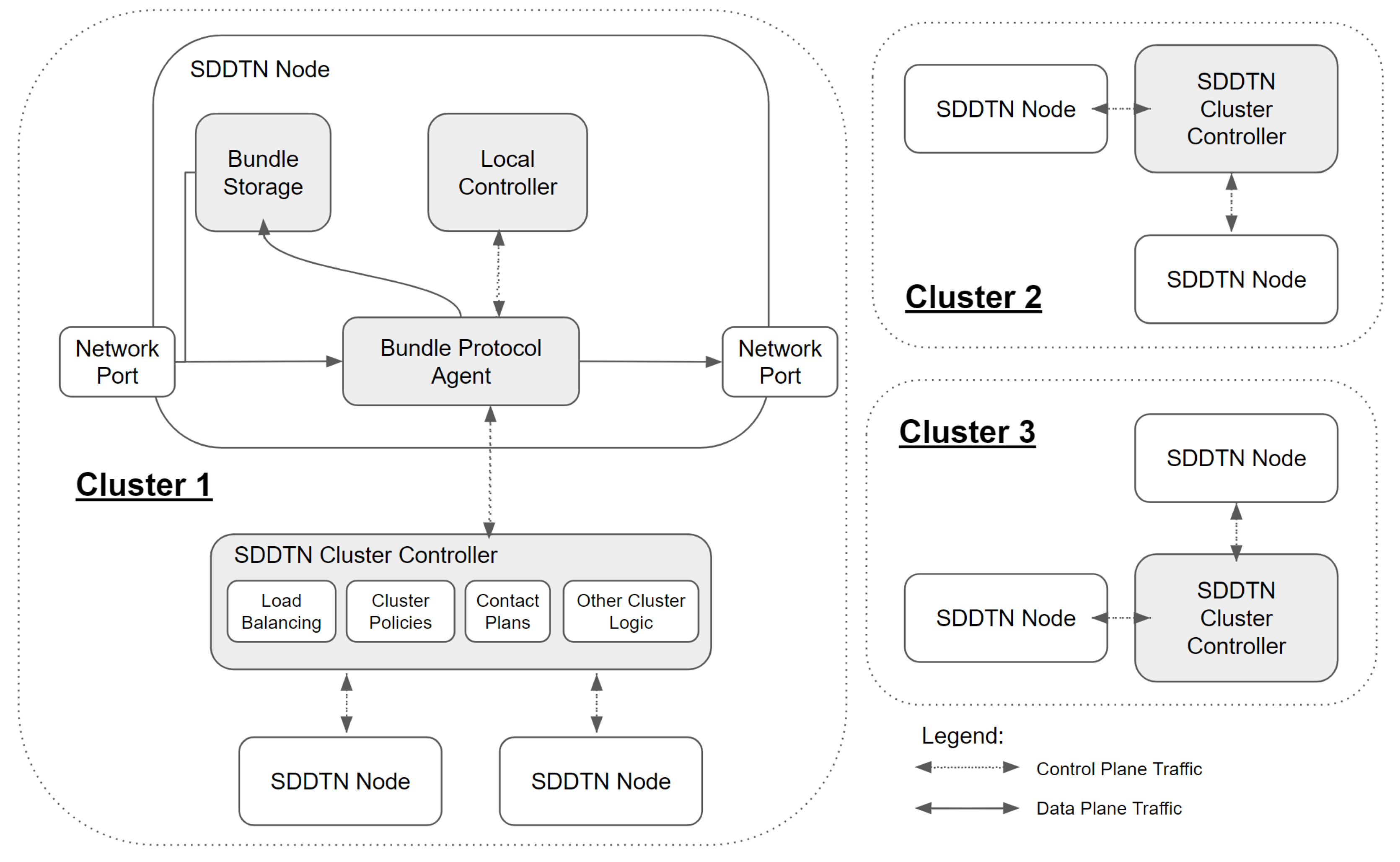
In our SDDTN architecture, we approach the issue of having reliable links between the controller and network nodes by dividing the network into clusters. As shown in Figure 6 within each cluster is a single SDDTN cluster controller and several SDDTN nodes. Each SDDTN node should have all the behavior of a regular DTN node as specified by the BP specification, in addition to having a control plane link to its respective cluster controller. Through this link SDDTN nodes are able to report relevant network status updates to the cluster controller. Subsequently, using local neighborhood information from nodes within its cluster, the controller is able to make decisions and propagate these decisions (such as generating and sending contact plans) to the nodes within its cluster. It is assumed that the clusters are organized in a manner where these control plane links are mostly reliable, although how this is achieved is outside the scope of this paper. It should be noted that there is a large body of literature on SDN clustering and controller placement algorithms [29,30,31], and that these clusters could also be determined in a similar manner to regions in the previously discussed DTN inter-regional routing method [26]. This architecture enables decision making that is more optimal than if nodes worked independently and provides reliable propagation of network updates through the control plane links. Additionally, while cluster decisions may be suboptimal compared to decisions made with global knowledge, this clustering approach enables shorter decision making times for large space DTN networks.
Additionally in this SDDTN architecture, to account for the event that the control plane link for a given SDDTN node is disrupted, each SDDTN node has its own form of a local controller that enables it to continue making decisions on its own. This local controller could potentially always be running providing secondary services alongside the cluster controller, or it could be used as a backup controller. The services that this local controller would provide are implementation specific but could include behavior such as opportunistic learning, e.g., OCGR, flooding algorithms, or routing based on machine learning methods.
4. Proof-of-Concept Background and Setup
We explored implementing such a SDDTN architecture through the development of a proof-of-concept SDDTN node in the form of a networking switch. Current BP implementations are software packages and there are no full hardware solutions, possibly due to the complexity of BP. We primarily investigated a hardware implementation due to its potential to provide increased bundle processing and forwarding rates compared to software implementations, which is in line with the goal of HDTN. In Section 4.1, we provide background information about P4, the language we chose to use to program the hardware. In Section 4.2, we provide details on the specific P4 program we aimed to implement. In Section 4.3, we provide information about the setup we used in the development of our hardware implementation.
4.1. Programmable Data Planes and P4
Traditional SDN network operators configure their control plane to manage the behavior of vendor-defined networking switches (the data plane). However, there are no vendor-defined switches that can understand BP. Therefore, processing bundles natively within hardware and creating a SDDTN node requires the capability of a relatively new networking paradigm for network operators: data plane programming. With data plane programming, network operators are able to customize the data plane for their specific use case, e.g., to program a data plane that is able to understand custom protocols. One of the data plane programming languages available is Programming Protocol-independent Packet Processors (P4). With the P4 language, code can be written to program data plane behavior and at compile-time a control plane Application Programming Interface (API) will be generated. Programs written in the P4 language can be compiled for a variety of targets, e.g., ASICs, FPGAs, and software switches, and have been used to implement a large variety of novel networking application in topics such as traffic management and congestion control, routing and forwarding, enabling machine learning, and network security [32]. For a brief overview of how the P4 language works and P4-specific terminology see Appendix A (Also see Available online: https://p4.org/learn/ (accessed on 1 September 2022) for more learning resources). The P4 language’s ability to configure both the data plane and control plane, its open source nature and large ecosystem, and its proven role in creating novel networking applications makes it an attractive choice as a tool to implement a SDDTN node.
However, P4 has a known limitation in handling variable-width fields that makes applying it to BP, a protocol with mostly variable-width fields, a non-trivial task (For more information, see Sections 7.1.6.4, 7.2.2, 8.9, and 13.8.2 of version 1.2.3 of the P4 language specification). A P4 program treats packets as a collection of headers which are user-defined and encompass the various header types that the user expects to handle, e.g., Ethernet headers and IP headers. Headers are a collection of user-defined fields, where a field is typically declared as a primitive bit<w> data type with a pre-defined field size of w bits. For example, an IPv4 source address field would be declared as a bit<32>. For packet fields that have variable-widths, there is a varbit<w> data type with a user-defined upper bound size of w bits. There are a restricted set of operations that can be performed on varbits that make it difficult to work with compared to fixed-width bitstrings: a varbit<w> can be assigned to another varbit<w> if w is the same, and varbits can be compared for equality [33]. Notable operations that are not currently possible include the ability to read bits from a varbit, modify bits within a varbit, and the ability to manually initialize a varbit [34]. These restrictions are not ideal for protocols like BP that rely on variable-width fields, however there are discussions in the P4 Language Design Working Group to add more operations to varbit types in future iterations of the language [34].
For handling variable-width fields, the suggested alternative to varbits is to declare several fixed-width headers, one each for every possible width that is expected to be encountered [35]. This works because fixed-width fields are less restricted in the operations that can be applied, however this increases the amount of coding overhead in order to manually handle all possible cases. A case study for what this looks like in practice can be seen in the work done to implement Meta4, a P4 application to monitor Domain Name System (DNS) traffic in the data plane for the Intel Tofino target [36]. Domain names have variable widths which proved to be a challenge as they had to account for both hardware memory constraints along with the P4 restrictions. In one of their P4 programs that contained 1,691 lines of code, there were approximately 800 lines of repetitive code dedicated towards parsing the domain names up to a maximum size of 90 bytes [37]. As BP has significantly more variable-width fields, and even fields that can be in different orderings, Meta4 serves as a useful baseline for what may be able to be achieved in parsing BP headers with P4.
4.2. Proof-of-Concept Motivation
The P4 program we aimed to create is one that would enable a switch to translate between BPv6 and BPv7. This task was chosen for two reasons. First, it was sufficiently complex to explore all aspects of the BP protocols, the P4 language, and networking hardware. A translator would need to be able to parse all BP fields, understand the semantics behind these fields, be able to modify fields as needed, properly update checksums, and send bundles forward; these are all tasks that a SDDTN node should also be able to do. Secondly, it would provide a potential real-world application for deployment on the ISS, which currently uses the ION software with BPv6. Updating software on the ISS can be a complicated endeavor and ION does not have compatibility between BP versions, so this translator could serve as a middlebox in communication with future BP nodes. Therefore, the task of creating a translator serves as an exploration in parsing BP in hardware via P4 programming, and could potentially aid the communications between legacy, current and future DTN nodes.
4.3. Development Setup
The P4 target used was the Intel Tofino (Available online: https://www.intel.com/content/www/us/en/products/network-io/programmable-ethernet-switch/tofino-series.html, accessed on 1 September 2022) programmable Ethernet switch application-specific integrated circuit (ASIC). The Tofino ASIC follows the PISA architecture discussed in Appendix A and is designed to deliver up to 100 GbE speeds. The target used was the first version of the Tofino ASIC, which is contained inside the Aurora 710 programmable switch from Netberg (Available online: https://netbergtw.com/products/aurora-710/, accessed on 1 September 2022). The Aurora switch utilized Intel’s P4 Studio SDE version 9.7.0 to compile the program. This target was chosen because, according to our experiences, it was a less restrictive subset of the P4 language and was easier to use compared to other hardware targets studied. In addition, the Aurora switch receives regular updates from Intel as updates are released.
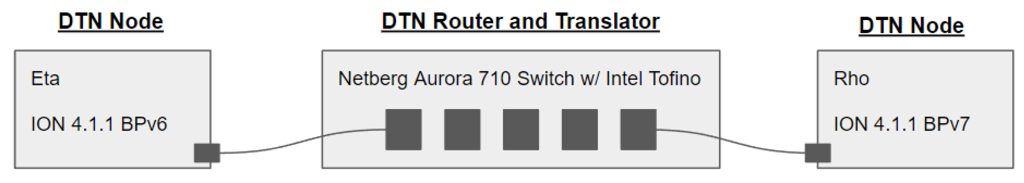
The configuration involved two endpoint computers, named Rho and Eta, connected to hardware ports on the Aurora 710 switch. Rho and Eta acted as DTN nodes generating or receiving bundles to be sent to its counterpart over UDP, IP, and Ethernet. Version 4.1.1 of the ION software implementation of DTN was installed on both endpoint nodes, which supports both BPv6 and BPv7 (configured respectively in installation). ION was chosen for development as it offers an application called bpchat, a command-line interface (CLI) chat function, which enabled quick confirmation of different bundle payloads. Figure 7 shows the setup, where the two DTN nodes, each running different versions of BP, are connected to the programmable switch.
5. Proof-of-Concept Results
We found that BPv6 and BPv7’s complex encoding scheme made building a protocol translator which encodes and decodes these protocols a difficult task. Although we were not able to produce a full set of BPv6 and BPv7 capabilities, we were able to demonstrate a bundle translator that would be useful for an initial SDDTN node. In Section 5.1 we discuss the high-level algorithm used for our translator. In Section 5.2 we discuss the constraints of our proof of concept and their causes. In Section 5.3 we showcase the capabilities and test the behavior of our proof of concept in different scenarios.
5.1. The P4 Algorithm
Our P4 program consists of three primary stages: (1) the parser stage which is responsible for interpreting incoming bits from bundles and representing them in structured fields, (2) the match-action pipeline which is where the translation logic is applied and fields are modified, “digest” data about the bundle is tracked to be later sent to the controller, and egress ports are determined using match-action tables that are initialized by a controller, and (3) the deparser stage which sends the digest data to the controller, recalculates and updates checksums, and emits the bundle out the egress port. Note that as shown in Figure 8, our parser was restricted to only handle the sets of protocols required for our experimental setup, i.e., Ethernet, IPv4, UDP, BPv6, and BPv7, as parsing other protocols such as TCP, LTP, and IPv6 were out of the scope of this work.
The details of these individual stages are explained here, with an overview of these steps shown in Algorithm 1 (Code to be made available pending release process). After Ethernet, IPv4, and UDP are appropriately parsed, in Step 1.4, our program uses the lookahead functionality to examine the upcoming 8-bits of data, which sends the parser to either the BPv6 parsing (if 0x06 is seen), or BPv7 parsing (if 0x9F is seen, the start code of a CBOR indefinite-length array). Implementing Step 1.5, where our parser actually interprets bundle bits and stores them into P4 fields, is where we faced the most issues due to the variable-width nature of BPv6 and BPv7 bundles; we explain this further in Section 5.2. As a result of these issues, the P4 fields and headers are fixed-width and are in a specific format that is not generalizable to all possible bundle configurations; a diagram of the bundles that our program is able to accept is shown in Figure 9 and Figure 10. After Step 1.5 is completed, the P4 program sets a flag that communicates to future stages of the P4 program which version of the bundle that was ingested. Step 1.7 marks the end of the parser stage where the bundle is accepted and the bundle is sent to the match-action pipeline for further processing. If any of the previous steps experienced an issue in parsing a bundle, the bundle would be rejected and dropped.
The match-action pipeline handles several important components for verifying parsing, initializing data to be sent to the SDN controller, modifying bundles, and applying logic received from the controller via match-action tables. Verifying the validity of bundle headers to ensure it was parsed or not parsed, Step 2.1, is something that in actuality happens throughout the various next steps of match-action pipeline as various fields are attempted to be used, but it is placed first for simplicity. Step 2.2 is responsible for storing any data that should be sent to the controller in a P4 struct, this can include data from any fields such as the bundle age or EIDs. Step 2.3 is where translation begins, new BP headers are declared (BPv7 if BPv6 was ingested into the switch, or vice versa), and data are transferred from one version of the BP headers to the new BP headers. Once the new headers are ready, in Step 2.4, the old BP headers are invalidated and the new BP headers are validated so that the translated bundle will be sent (An implementation detail to note is that only the headers for the payload data are reused for both BPv6 and BPv7, so that they have no need to be invalidated and copied over). Then, the length fields in the IPv4 and UDP headers are updated to accurately reflect the new bundle size (since BPv6 and BPv7 headers have different sizes). Lastly, an egress port for this bundle is determined by matching data to the match-action table entries; this table is filled by the SDN controller.
In the deparser stage, data are sent to the controller and final updates are done before sending bundles out of the switch. In Step 3.1, the struct of data that were initialized in Step 2.2 is finally sent out of the switch via the control plane link to the SDN controller. In Steps 3.2 and 3.3, the IPv4 and UDP checksums are updated because the bundle was modified and the checksums are the bundle’s integrity by the endpoint. Finally, the bundle is sent out of the switch using the egress port that was determined in Step 2.7.
| Algorithm 1 P4 Bundle Translator Algorithm. |
Step 1: Parser
|
5.2. Design Constraints
One complexity faced was the parsing of SDNV fields due to the inability to determine the width of a SDNV field unless the entire field is examined. This is different from other protocols that use variable-width fields, in which there is usually a fixed-width field that provides information about the actual width of the variable-width fields. For example, in IPv4 there are optional fields and the total size of these optional fields can be deduced by examining the Internet Header Length (IHL) field. With SDNV-encoded fields, the P4 parser would need to use the lookahead function and recursively examine octets of bits until it encounters an octet with an MSB of 0, up to a maximum of eight octets for each field. Once the actual size of a field is determined, it would need to be assigned to the fixed-width header that handles the case of the exact size needed for that specific BP field (using the variable-width P4 workaround). In our attempts to implement the parsing of a basic SDNV field using lookahead we found that there was undefined behavior occurring in the parser stage that broke the piece of our deparser stage where the checksums are calculated. This bug was discovered to be internal to the Intel software and will be fixed in SDE 9.11.0. Therefore, in the proof of concept several BPv6 fields were assumed to be a certain size to avoid this bug and having to handle all possible lengths for SDNV fields.
Initially, the plan was to use incremental checksum calculations, where if certain fields are modified the checksum only needs to be updated to account for these modified fields rather than recomputing the checksum from scratch [38]. Incremental checksum calculations are a built-in functionality (extern in P4 terminology) of the Tofino target, however, it was not interacting properly with the lookaheads used in the attempts to parse SDNVs (as a result of the bug). As an alternative to these incremental checksums, we resorted to calculating the entire checksum from scratch. A downside of this approach is that the entire bundle must then be parsed, including the entire payload, to incorporate these fields into the checksum calculations. This is an issue as payloads are inherently variable-width, which means that the fixed-width workaround must be used to parse these payloads; therefore, the size of a payload that can be accepted in the bundle translator is limited by 13 bytes. Handling payloads of any size would be possible if an incremental checksum approach was able to be used.
Parsing the CBOR encoded fields of BPv7 also posed a challenge. In the CBOR specification, it is stated that “A CBOR decoder implementation can be based on a jump table with all 256 defined values for the initial byte (Table 7). A decoder in a constrained implementation can instead use the structure of the initial byte and following bytes for more compact code (see Appendix C for a rough impression of how this could look)” [22] suggesting that either a hardcoded jump table can be used to quickly determine the CBOR data type, or the provided compact algorithm can be used if memory is a limitation. However, due to the limited memory available and lack of a table data type available in the parser stage of the Aurora 710 switch, a jump table would not be possible to implement in our target. Therefore an adaptation of the compact decoding algorithm was attempted. However, the limited control flow structures available in the parser stage within the P4 language made adapting this algorithm a nontrivial task: conditional branching can only occur at the end of every parser state, and any looping must be done in a recursive manner through the various parsing states. Additionally, in the Tofino target, although there are variables available for use to keep track of state, there is only “write-once” functionality, meaning that executing code analogous to i = i + 1 multiple times has undefined behavior as to what the value of i is. Fortunately, there is a ParserCounter Tofino extern available for use as a counter variable in the parser stage. Attempts to utilizing this extern to loop through parsing of a CBOR field led to strange behaviors. For example, where certain fields were being modified and parser states were executed in conditions where they should not have been. It is not clear if this was due to user error or an issue with the environment and therefore another compromise was made to assume the size of most of the BPv7 fields, as done with BPv6 fields.
5.3. Proof-of-Concept Evaluation
Despite these design constraints, our proof-of-concept translator is able to execute the basic functionality required to enable communication between two incompatible DTN nodes. The accepted bundles must be of a specific format which is based on the format of bundles outputted by ION’s bpchat program, the environment used in the development of this program (Although this iteration of the translator was designed for one specific bundle format, the translator can be adapted to work with other bundle formats). The proof of concept handles variable-widths for the bundle payload as well as the BPv7 creation timestamp: payloads up to 13 bytes are supported, which can be extended by repeating the code pattern, along with the maximum possible width of a BPv7 creation timestamp. The outputs of the translator are the primary block and the payload block which are the required bundle blocks. The current state of the implementation represents the first steps towards SDDTN.
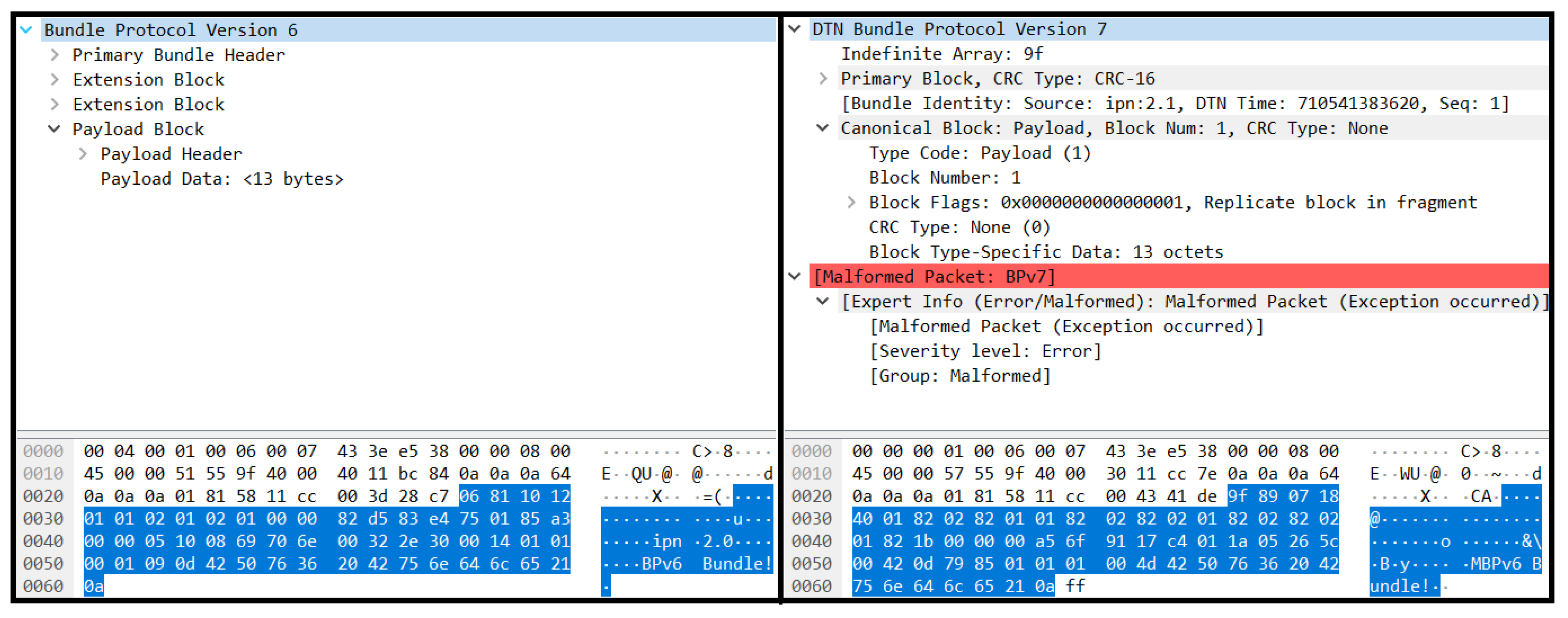
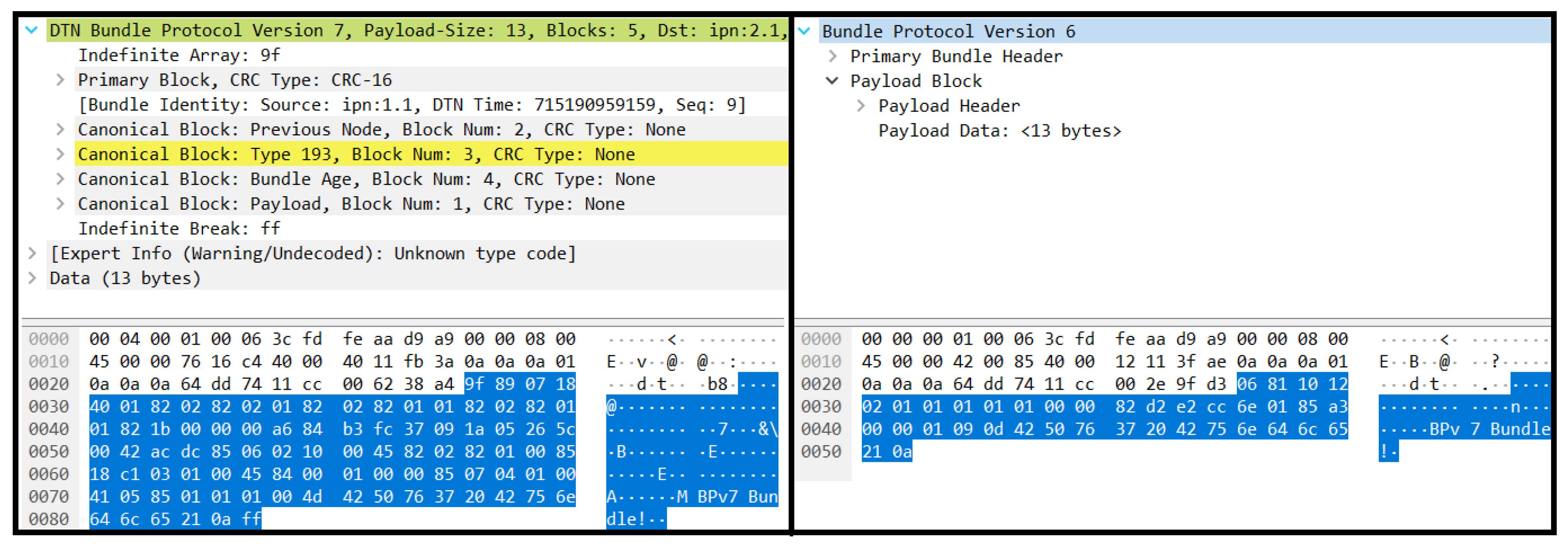
We evaluated the translation capabilities by determining whether Rho and Eta would be able to communicate in their respective bpchat programs despite being DTN nodes utilizing different versions of the BP. From the end user perspective, this was a success as Rho and Eta could interactively chat in bpchat without any sign of an error (as long as each message was kept to under 14 bytes long). However, upon further inspection of the packet captures, shown in Figure 11 and Figure 12, we sometimes saw a “Malformed Packet” error displayed in Wireshark in the BPv6 to BPv7 translation that may be caused by a slight formatting error from the translator’s output bundle mismatching a detail in the BP specification. Despite this, the end node was still able to receive and decode the translated bundle. Additionally, Wireshark marked a BPv7 extension block in yellow to indicate an unknown node; this was due to ION using an unofficial extension block type. An important aspect to note is that IPv4 and UDP checksums were properly updated, which was required for the end-nodes to properly receive the bundle.
In addition to the above tests which were based on the experimental setup using in the development of this program, we also examined how the translator would behave with a node utilizing HDTN as its DTN implementation instead of ION to understand its interoperability with other systems. To do this, Eta had both ION and HDTN with BPv6 installed, and Rho had both ION and HDTN with BPv7 installed. Then we ran various basic interoperability tests and examined if bundles could be sent and properly decoded after passing through the translator, testing configurations such as ION BPv6 to HDTN BPv7 and HDTN BPv6 to ION BPv7. As expected, if an HDTN node generated bundles to send to the translator, the translator failed to produce a valid bundle for ION. This is because the format of bundles generated by HDTN did not perfectly match the bundles that the translator expected to see. However, when an HDTN node received a translated bundle that originated from an ION node, it was able to receive and decode the bundle; this was a success in terms that HDTN could understand the specific BP version.
Although this proof of concept was unable to handle bundles in all cases, certain promising capabilities were demonstrated. Notably, this device was able to parse bundle fields, understand the semantics behind these fields, modify fields as needed, update UDP and IPv4 checksums, send telemetry to a SDN controller, and coordinate with a SDN controller to make forwarding decisions. These are all primitive functionalities that would be required for a SDDTN node that needs to process bundles, communicate information about the bundles and network behavior to a controller, and respond accordingly to decisions made by an SDDTN controller. Additionally, further development of this proof of concept could make it a useful tool to aid interoperability when deployed as a middlebox between two nodes using different versions of BP, as an alternative to updating the nodes to have the same version of BP (which may or may not be possible due to various physical or social limitations). These are promising results that make further investigation in using P4 for DTN a worthwhile endeavor.
6. Discussion
Both SDDTN and the BP translator have a lot of potential for improvements. Past work in improving the scalability of DTN was explained, i.e., OCGR, inter-regional routing, SDN IP-layer load balancing, and the Last Mile TEN SDN for DTN architecture. These ideas are not necessarily incompatible with the proposed SDDTN architecture, as many of these concepts can be incorporated as components within the SDDTN architecture. For example, a SDDTN node can use OCGR and send this new information to the SDDTN controller which can propagate this information effectively. There is future work to be done in exploring how these various approaches to scaling DTN networks can be combined in a synergistic manner. Additionally, the details of how clusters would be organized in a SDDTN network were not explored. There are numerous ways this could be performed, such as through manual human planning, machine learning algorithms, or game theory. There is a significant amount of work in the field of SDN tackling this issue of controller placement and clustering, and adapting these advancements to the space DTN environment would aid a SDDTN network in its ability to scale.
Although the proof-of-concept P4 DTN implementation was able to demonstrate novel capabilities, several components should be improved before deploying to the field. This was largely due to the issues we faced with the variable-width fields of BP, however the ideas we presented and the different implementations attempted are not exhaustive. Therefore, we believe it is still possible to use P4 to implement hardware that is able to more rigorously handle BP. This could be possible through the use of other P4 targets, modified algorithms, through improvements of the Tofino target and provided externs, or through improvements in the P4 language itself. Alternative tools to programming or creating hardware should also be considered. Details of BP that were not handled in this proof-of-concept translator include a general codec for SDNV and CBOR fields, BPv7 cyclic redundancy checks (CRC) for each block, accounting for both standard and CBHE encoded BPv6 bundles, handling different orderings of extension blocks, and determining what a proper mapping of data between BPv6 and BPv7 should look like. Important aspects of DTN and BP that were outside the scope of this work include handling other transport layers such as TCP and LTP, handling Bundle Protocol Security (BPSec), and improving bundle routing through learning of contacts, EIDs, IP addresses, and MAC addresses. Additionally, there is exciting work to be done in the far future if a fully featured DTN node was able to be implemented in P4. For example, previous work has demonstrated it is possible to use P4 to implement a router that can use machine learning to learn network behavior at both the individual node level and at the SDN controller level [39]. Successful application of these router machine learning concepts to a SDDTN node could enable a cognitive DTN (CDTN) node that is able to sense, react, and dynamically respond to changes in the network that lead to significantly improved routing that may not be possible with traditional routing algorithms. A CDTN and other cognitive forms of network communications in the space DTN environment are desirable technology for NASA and its mission to improve space network scalability [40].
7. Conclusions
A SDDTN architecture is proposed as a solution to the scalability issue that space DTN networks currently face. Current space DTN networks rely on CGR and proper distribution of contact plans to ensure that DTN nodes are able to route bundles in the challenged space networking environment. The SDDTN architecture aims to solve the issue of contact plan distribution in this highly dynamic environment with intermittent links by dividing the network into smaller clusters. Benefits of this clustering approach that SDDTN provides includes more reliable contact plan distribution, reduced CGR computation runtime, and the ability to accumulate information from individual nodes within a cluster to make more optimal decisions.
The BP translator proof of concept showed one way that SDN hardware, P4, and the BP headers are able to coexist with one another. This served as both a test for what P4 may be able to contribute to DTN network programmability and also as a potential real-world application in aiding interoperability between DTN nodes using different versions of BP. We showed that a switch can be used as more than just a bundle relay device, but as a component in the DTN network that provides additional routing and protocol translation capabilities.
A fully featured implementation was ultimately not able to be produced due to a myriad of issues that stem from a design incompatibility between BP’s complex encoding scheme and flexible bundle layout, and the P4 languages support for variable-width fields. The details of these issues and the underlying cause are enumerated which may serve as a useful reference for those interested in the impact of BP’s encoding scheme on resource-constrained development environments.
Future directions of research in further improving this hardware implementation, space DTN scalability and SDDTN are also shared. A successful execution of a SDDTN and with a fully programmable DTN network stack would advance the future of large-scale space DTN networks by enabling cognitive nodes, elimination of network bottlenecks, and reliable routing capabilities at large scale.
Author Contributions
Conceptualization, D.T., S.B. and R.D.; methodology, S.B.; software, D.T. and S.B.; validation, D.T. and S.B.; investigation, D.T.; resources, S.B.; writing—original draft preparation, D.T.; writing—review and editing, D.T., S.B. and R.D.; visualization, D.T. and S.B.; supervision, R.D. All authors have read and agreed to the published version of the manuscript.
Funding
This research was funded by the NASA Glenn Research Center and the NASA Space Communications and Navigation (SCaN) program.
Data Availability Statement
Not applicable.
Acknowledgments
The authors would like to thank the NASA GRC HDTN team, Cognitive Communications team, Space Communications and Navigation Internship Project (SIP) team, and DTN researchers at other NASA facilities for their provided resources and guidance, which was instrumental in laying the groundwork for this research. We would also like to thank Alan Hylton, Dennis Iannicca, and John Nowakowski for their critical review and comments which improved and clarified this manuscript.
Conflicts of Interest
The authors declare no conflict of interest.
Appendix A. Overview of P4
The most current iteration of the P4 language and abstraction specification is P4, introduced in 2016. The P4 language has a core library that provides a minimal set of functionality by design. This language is extended by vendors providing externs to provide extra functionality to users creating P4 programs for a specific compiler target (e.g., different hardware architectures, software switches, etc.). These externs can include things such as registers, counters, meters, hash generators, and checksum calculators. The existence of externs and target limitations means that P4 programs are not necessarily compatible between targets. However, there are standardized data plane processing architectures to promote cross-compatibility between targets by providing a common abstraction model, like Protocol Independent Switch Architecture (PISA). The PISA architecture divides the data plane programming process into three main pieces: a parser, match-action pipeline, and deparser [32].
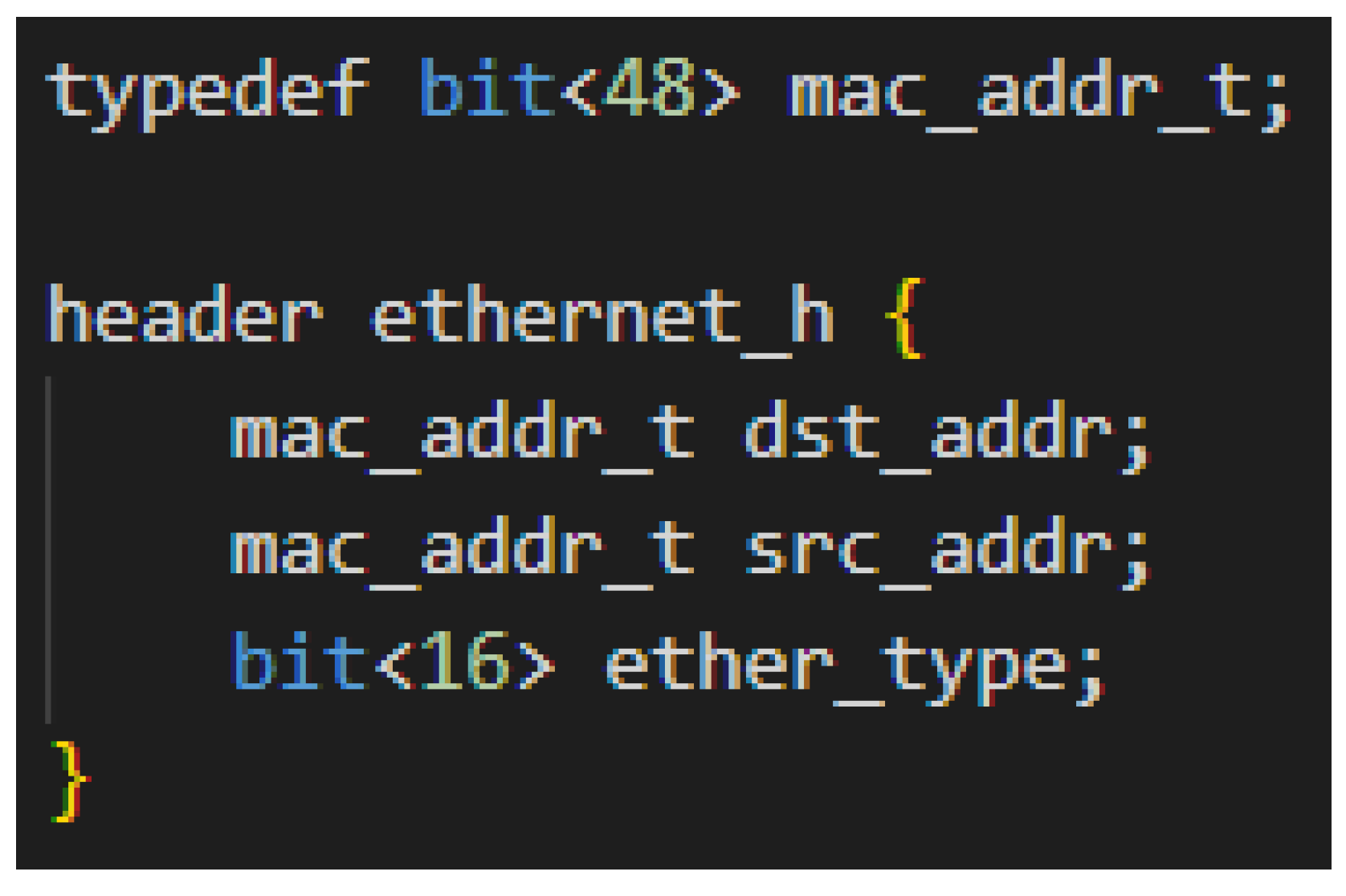
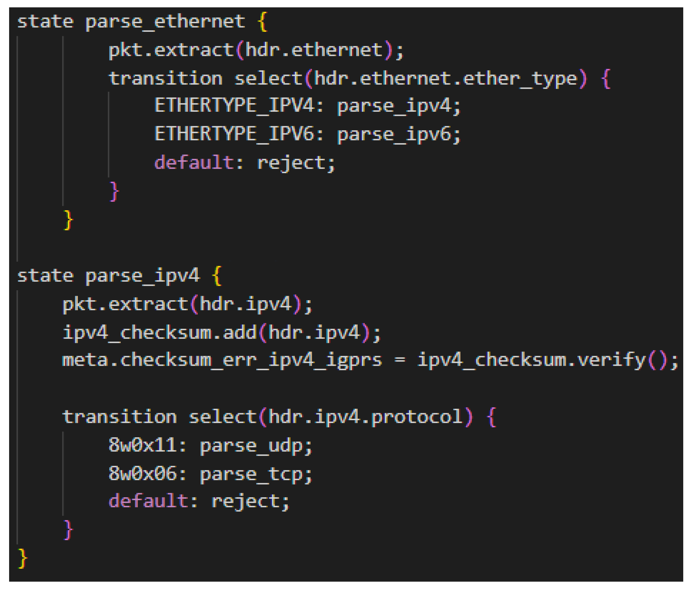
The parser is a finite state machine that takes an incoming packet and parses it into well-defined data types based upon the network headers provided. A P4 program must specify the headers that it expects to encounter and support in any incoming packet. Headers are groups of fields, where fields have a name and a data type. See Figure A1 for an example declaration of an Ethernet header. All packets begin in the “start” parser state and either end in the "accept" state to be sent to the match-action pipeline, or to the “reject” state to be dropped. As packets flow through the state machine, fields of the packet are extracted into the P4 header variables from top to bottom. As these headers are extracted and read, the state machine can make conditional state transitions based on information extracted from packet headers [32]. For example, after Ethernet headers are extracted, the Ethertype field can be examined to determine whether to transition to the IPv4 or IPv6 parsing state. Or a P4 program can examine bits that have not been extracted, such as peeking into the beginning of a bundle to determine whether to transition to the BPv6 or BPv7 parsing state. Figure A2 shows an example of P4 parser code.
This packet is then sent to the match-action pipeline where the majority of the processing logic is held. The match-action pipeline contains the primary processing and forwarding logic of the data plane. It is in this stage of the program where tables can be created to rows of keys and actions. An incoming packet is matched to a row with its designated matching key (e.g., IPv4 address matched to keys with longest-prefix match (LPM)), and then actions are performed here on the packet (e.g., dropping the packet or declaring what egress port this packet should go to). The actions that can be performed are custom defined and can involve manipulating the entire packet. This match-action pipeline is also where the control plane can directly interface with the data plane to manipulate a switch’s behavior. Once a P4 program is compiled and running on a target, the control plane is able to send messages to the data plane via an API to manipulate the rows of these tables. It is in this way that the control plane is able to control the logic of the data plane, however it is up to the data plane programmer to provide tables that provide the sufficient amount of control required by the control plane [32]. The P4 program in Figure A3 showcases a match-action pipeline that has a simple table for IPv4 forwarding. This table matches packets to rows based on IPv4 destination addresses. When a match is found, it is assigned a specified egress port.
Figure A1.
Example P4 Header Declaration.

Figure A2.
Example P4 Parser Code.

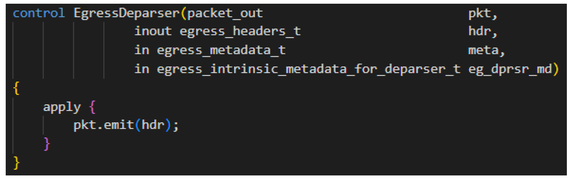
After a packet exits the match-action pipeline, it is sent to the deparser [32]. The deparser stage handles any final packet processing logic and emits the packet onto the wire. For example, the deparser can perform checksum updates, e.g., TCP, UDP or IP checksums, if the packet was manipulated at any point in the pipeline. Packets are sent out by simply calling a final emit function. Note, any work to specify the egress port for the packet would have been done in an earlier stage. Figure A4 shows a simple deparser that emits all valid extracted headers and any data that follow the headers.
Figure A3.
Example Match-Action Pipeline.

Figure A4.
Example Deparser.

References
- LunaNet Interoperability Specification Document Version 4; Technical Report; National Aeronautics and Space Administration and European Space Agency: Washington, DC, USA, 2022.
- Otero, D.G. ESA Moonlight Initiative. Presented at IPNSIG Academy. 2022. Available online: https://ipnsig.org/wp-content/uploads/2022/11/IPNSIG-ESA-Moonlight-overview-Nov-2022-1.pdf (accessed on 26 September 2022).
- Cerf, V.; Burleigh, S.; Hooke, A.; Torgerson, L.; Durst, R.; Scott, K.; Fall, K.; Weiss, H. Delay-Tolerant Networking Architecture; RFC 4838; IETF: Fremont, CA, USA, 2007. [Google Scholar] [CrossRef] [Green Version]
- Demmer, M. A Delay Tolerant Networking and System Architecture for Developing Regions. Ph.D. Thesis, University of California, Berkeley, CA, USA, 2008. [Google Scholar]
- Basciano, T.; Pohlchuck, B.; Shamburger, N.M. Application of Delay Tolerant Networking on the International Space Station. In Proceedings of the ISS Research and Development Conference, Atlanta, GA, USA, 29 July–1 August 2019. [Google Scholar]
- Fraire, J.A.; De Jonckère, O.; Burleigh, S. Routing in the Space Internet: A contact graph routing tutorial. J. Netw. Comput. Appl. 2021, 174, 102884. [Google Scholar] [CrossRef]
- Cerf, V.; Kaneko, Y.; Burleigh, S.; Suzuki, K.; Luque, M. IPNSIG Strategy Working Group Report: A Strategy Toward a Solar System Internet for Humanity; IPNSIG: Arlington, VA, USA, 2021. [Google Scholar]
- Fall, K. A Delay-Tolerant Network Architecture for Challenged Internets. In Proceedings of the 2003 Conference on Applications, Technologies, Architectures, and Protocols for Computer Communications, SIGCOMM ’03, Karlsruhe, Germany, 25–29 August 2003; Association for Computing Machinery: New York, NY, USA, 2003; pp. 27–34. [Google Scholar] [CrossRef] [Green Version]
- Sipos, B.; Demmer, M.; Ott, J.; Perreault, S. Delay-Tolerant Networking TCP Convergence-Layer Protocol Version 4; RFC 9174; IETF: Fremont, CA, USA, 2022. [Google Scholar] [CrossRef]
- Scott, K.; Burleigh, S. Bundle Protocol Specification; RFC 5050; IETF: Fremont, CA, USA, 2007. [Google Scholar] [CrossRef]
- Burleigh, S.; Fall, K.; Birrane, E.J. Bundle Protocol Version 7; RFC 9171; IETF: Fremont, CA, USA, 2022. [Google Scholar] [CrossRef]
- NASA Jet Propulsion Laboratory. Interplanetary Overlay Network (ION). Available online: https://sourceforge.net/projects/ion-dtn/ (accessed on 1 September 2022).
- The Consultative Committee for Space Data Systems. Licklider Transmission Protocol (LTP) for CCSDS; CCSDS Blue Book; CCSDS: Washington, DC, USA, 2015. [Google Scholar]
- Burleigh, S. Contact Graph Routing. 2009. Available online: https://tools.ietf.org/html/draft-burleigh-dtnrg-cgr-00 (accessed on 1 September 2022).
- NASA Glenn Research Center. High Rate Delay Tolerant Networking (HDTN). Available online: https://www1.grc.nasa.gov/space/scan/acs/tech-studies/dtn/ (accessed on 1 September 2022).
- Hylton, A.; Raible, D. High Data Rate Architecture (HiDRA). In Proceedings of the Ka and Broadband Communications Conference 2016, Cleveland, OH, USA, 17–20 October 2016. [Google Scholar]
- Hylton, A.; Raible, D.; Clark, G.; Dudukovich, R.; Tomko, B.; Burke, L. Rising above the cloud: Toward high-rate delay-tolerant networking in low earth orbit. In Proceedings of the 37th International Communications Satellite Systems Conference (ICSSC-2019), Okinawa, Japan, 29 October–1 November 2019; pp. 1–17. [Google Scholar] [CrossRef]
- Hylton, A.; Cleveland, J.; Dudukovich, R.; Iannicca, D.; Kortas, N.; LaFuente, B.; Nowakowski, J.; Raible, D.; Short, B.; Tomko, B.; et al. New Horizons for a Practical and Performance-Optimized Solar System Internet. In Proceedings of the IEEE Aerospace Conference 2022, Big Sky, MT, USA, 5–12 March 2022. [Google Scholar]
- Raible, D.; Dudukovich, R.; Tomko, B.; Kortas, N.; LaFuente, B.; Iannicca, D.; Basciano, T.; Pohlchuck, W.; Deaton, J.; Hylton, A.; et al. Developing High Performance Space Networking Capabilities for the International Space Station and Beyond; Technical Memorandum; NASA: Washington, DC, USA, 2022.
- Eddy, W.; Davies, E.B. Using Self-Delimiting Numeric Values in Protocols; RFC 6256; IETF: Fremont, CA, USA, 2011. [Google Scholar] [CrossRef] [Green Version]
- Burleigh, S. Compressed Bundle Header Encoding (CBHE); RFC 6260; IETF: Fremont, CA, USA, 2011. [Google Scholar] [CrossRef]
- Bormann, C.; Hoffman, P.E. Concise Binary Object Representation (CBOR); RFC 8949; IETF: Fremont, CA, USA, 2020. [Google Scholar] [CrossRef]
- Jain, S.; Fall, K.; Patra, R. Routing in a Delay Tolerant Network. In Proceedings of the 2004 Conference on Applications, Technologies, Architectures, and Protocols for Computer Communications, Portland, OR, USA, 30 August–3 September 2004; Association for Computing Machinery: New York, NY, USA, 2004; pp. 145–158. [Google Scholar] [CrossRef] [Green Version]
- Jones, E.P.C.; Li, L.; Ward, P.A.S. Practical Routing in Delay-Tolerant Networks. In Proceedings of the 2005 ACM SIGCOMM Workshop on Delay-Tolerant Networking, Philadelphia, PA, USA, 26 August 2005; Association for Computing Machinery: New York, NY, USA, 2005; pp. 237–243. [Google Scholar] [CrossRef] [Green Version]
- Burleigh, S.; Caini, C.; Messina, J.J.; Rodolfi, M. Toward a unified routing framework for delay-tolerant networking. In Proceedings of the 2016 IEEE International Conference on Wireless for Space and Extreme Environments (WiSEE), Aachen, Germany, 26–29 September 2016; IEEE: Piscataway, NJ, USA, 2016; pp. 82–86. [Google Scholar]
- Alessi, N. Hierarchical Inter-Regional Routing Algorithm for Interplanetary Networks. Master’s Thesis, University of Bologna, Bologna, Italy, 2019. [Google Scholar]
- Booth, S.; Hylton, A.; Dudukovich, R.; Kortas, N.; LaFuente, B.; Tomko, B. Alleviating Bundle Throughput Constriction for Delay Tolerant Networking (DTN) Bundles with Software Defined Networking (SDN). In Proceedings of the SPACOMM 2022, the Fourteenth International Conference on Advances in Satellite and Space Communications, Barcelona, Spain, 24–28 April 2022. [Google Scholar]
- Zacarias, I.; Gaspary, L.; Kohl, A.; Fernandes, R.; Stocchero, J.; Pignaton de Freitas, E. Combining Software-Defined and Delay-Tolerant Approaches in Last-Mile Tactical Edge Networking. IEEE Commun. Mag. 2017, 55, 22–29. [Google Scholar] [CrossRef]
- Tao, P.; Ying, C.; Sun, Z.; Tan, S.; Wang, P.; Sun, Z. The Controller Placement of Software-Defined Networks Based on Minimum Delay and Load Balancing. In Proceedings of the 2018 IEEE 16th Intl Conf on Dependable, Autonomic and Secure Computing, 16th Intl Conf on Pervasive Intelligence and Computing, 4th Intl Conf on Big Data Intelligence and Computing and Cyber Science and Technology Congress(DASC/PiCom/DataCom/CyberSciTech), Athens, Greece, 12–15 August 2018; pp. 310–313. [Google Scholar] [CrossRef]
- Killi, B.P.R.; Reddy, E.A.; Rao, S.V. Cooperative game theory based network partitioning for controller placement in SDN. In Proceedings of the 2018 10th International Conference on Communication Systems & Networks (COMSNETS), Bengaluru, India, 3–7 January 2018; pp. 105–112. [Google Scholar] [CrossRef]
- Isong, B.; Molose, R.R.S.; Abu-Mahfouz, A.M.; Dladlu, N. Comprehensive Review of SDN Controller Placement Strategies. IEEE Access 2020, 8, 170070–170092. [Google Scholar] [CrossRef]
- Hauser, F.; Häberle, M.; Merling, D.; Lindner, S.; Gurevich, V.; Zeiger, F.; Frank, R.; Menth, M. A Survey on Data Plane Programming with P4: Fundamentals, Advances, and Applied Research. arXiv 2021, arXiv:2101.10632. [Google Scholar] [CrossRef]
- The P4 Language Consortium. P4_16 Language Specification Version 1.2.3. Available online: https://p4.org/p4-spec/docs/P4-16-v-1.2.3.html (accessed on 1 September 2022).
- Fingerhut, A. P4lang/P4-Spec: Issue #264 Define New Operations on Varbits. Available online: https://github.com/p4lang/p4-spec/issues/264 (accessed on 1 September 2022).
- Fingerhut, A. Guide to Handling Variable Length Headers in P4. Available online: https://github.com/jafingerhut/p4-guide/tree/master/variable-length-header (accessed on 1 September 2022).
- Kim, J.; Kim, H.; Rexford, J. Analyzing Traffic by Domain Name in the Data Plane. In Proceedings of the ACM SIGCOMM Symposium on SDN Research (SOSR), Virtual, 11–12 October 2021; Association for Computing Machinery: New York, NY, USA, 2021; pp. 1–12. [Google Scholar] [CrossRef]
- Kim, J.; Kim, H.; Rexford, J. Meta4: Netassay_tunnel_j8.p4. Available online: https://github.com/hyojoonkim/Meta4/blob/main/P4/netassay_tunnel_j8.p4 (accessed on 1 September 2022).
- Rijsinghani, A. Computation of the Internet Checksum via Incremental Update; RFC 1624; IETF: Fremont, CA, USA, 1994. [Google Scholar] [CrossRef]
- Musumeci, F.; Fidanci, A.C.; Paolucci, F.; Cugini, F.; Tornatore, M. Machine-Learning-Enabled DDoS Attacks Detection in P4 Programmable Networks. J. Netw. Syst. Manag. 2022, 30, 21. [Google Scholar] [CrossRef]
- NASA Space Communications and Navigation. Cognitive Communications Project. Available online: https://www1.grc.nasa.gov/space/scan/acs/cognitive-communications/ (accessed on 1 September 2022).
Figure 1.
Bundle Protocol network stack. Blue dotted lines show OSI model layer 4 and up for a typical DTN network stack. Red dashed lines show the typical layer 4 and up for Earth communications (without BP). Black solid lines show the underlying network layers.
Figure 1.
Bundle Protocol network stack. Blue dotted lines show OSI model layer 4 and up for a typical DTN network stack. Red dashed lines show the typical layer 4 and up for Earth communications (without BP). Black solid lines show the underlying network layers.

Figure 2.
Example SDNV encoding where the blue, yellow, and green highlights a group of 7 bits that is modified to become an octet of bits. The Most Significant Bit (bolded and underlined) in the first two octets are a 1 indicating that this is not the last octet within this piece of data.
Figure 2.
Example SDNV encoding where the blue, yellow, and green highlights a group of 7 bits that is modified to become an octet of bits. The Most Significant Bit (bolded and underlined) in the first two octets are a 1 indicating that this is not the last octet within this piece of data.

Figure 3.
Layout of BPv6 bundles. Very few fields have a defined bit width (denoted with a solid outline). Most fields have a bit width that is only known until it is parsed using the SDNV encoded scheme (denoted with a bold dashed outline). Other fields have a width encoded by a field preceding it (denoted with a non-bold dashed outline).

Figure 4.
Decoding of BPv7 bundle (left: Wireshark capture of BPv7 bundle with primary block bytes highlighted; right: A manual decoding of the CBOR-encoded bundle fields).
Figure 4.
Decoding of BPv7 bundle (left: Wireshark capture of BPv7 bundle with primary block bytes highlighted; right: A manual decoding of the CBOR-encoded bundle fields).

Figure 5.
Layout of BPv7 bundles. A bundle is encoded as an indefinite–length array of blocks, and blocks are encoded as definite–length arrays of fields. The size of each field is determined by its data type and defined length in its initial byte (shown in parentheses).
Figure 5.
Layout of BPv7 bundles. A bundle is encoded as an indefinite–length array of blocks, and blocks are encoded as definite–length arrays of fields. The size of each field is determined by its data type and defined length in its initial byte (shown in parentheses).

Figure 6.
A Software-Defined Delay Tolerant Network architecture, with three clusters, each containing an SDDTN controller managing SDDTN nodes via control plane links. A SDDTN node has all the behaviors of a typical DTN node, dictated by the abstract Bundle Protocol Agent, and also has communication with a local controller.

Figure 7.
Physical configuration of setup.

Figure 8.
Parser state machine for Bundle Translator. The parser stage of a P4 program is coded as a series of states that are transitioned between using data from fields of the packet being parsed.
Figure 8.
Parser state machine for Bundle Translator. The parser stage of a P4 program is coded as a series of states that are transitioned between using data from fields of the packet being parsed.

Figure 9.
Expected format for incoming BPv6 bundles. A Previous Hop Insertion Block and Bundle Age Block are the only extension blocks expected, in this specific order. Additionally, currently only payloads up to 13 bytes are expected. There is undefined behavior for any bundles sent to the bundle translator that do not match this format.

Figure 10.
Expected format for incoming BPv7 bundles. Note that in the primary block, the creation timestamp can be between 88 to 96 bytes. A Previous Node Block, Experimental Class of Service Block, and Bundle Age Block are the only extension blocks expected, in this specific order. Additionally, currently only payloads up to 13 bytes are expected. There is undefined behavior for any bundles sent to the bundle translator that do not match this format.

Figure 11.
Translation of BPv6 to BPv7. The bundle layer bytes are highlighted in blue.

Figure 12.
Translation of BPv7 to BPv6. The bundle layer bytes are highlighted in blue.

Disclaimer/Publisher’s Note: The statements, opinions and data contained in all publications are solely those of the individual author(s) and contributor(s) and not of MDPI and/or the editor(s). MDPI and/or the editor(s) disclaim responsibility for any injury to people or property resulting from any ideas, methods, instructions or products referred to in the content. |
© 2022 by the authors. Licensee MDPI, Basel, Switzerland. This article is an open access article distributed under the terms and conditions of the Creative Commons Attribution (CC BY) license (https://creativecommons.org/licenses/by/4.0/).
Share and Cite
MDPI and ACS Style
Ta, D.; Booth, S.; Dudukovich, R. Towards Software-Defined Delay Tolerant Networks. Network 2023, 3, 15-38. https://doi.org/10.3390/network3010002
AMA Style
Ta D, Booth S, Dudukovich R. Towards Software-Defined Delay Tolerant Networks. Network. 2023; 3(1):15-38. https://doi.org/10.3390/network3010002
Chicago/Turabian StyleTa, Dominick, Stephanie Booth, and Rachel Dudukovich. 2023. "Towards Software-Defined Delay Tolerant Networks" Network 3, no. 1: 15-38. https://doi.org/10.3390/network3010002